
Designing a full-wave loop antenna for 7 MHz
It has been a few years since my last HF antennas fell down. That coincided with a period of no interest in amateur radio (on my part). I’ve decided to put up another antenna and maybe give HF radio another try.
The antenna.
I’ve had good results in the past with a 40m full-wave loop, and this fits nicely in the space I have available. I’ll be fitting it into a rectangle with the long sides running East-West, and the short sides North-South.
The far end of the antenna will be a short side, 6m above ground. The North-most long side will rise from 6m at the far end to 12m close to the feed point. The next short side will slope from 12m to 8m, and the southernmost long side runs from 8m to 6m at the far end.
The effect is a slight in-plane twist, with a built-in slope towards the west. The short sides will be ~4.6m long, and the long sides ~15.75m for a total length of 40.7 meters. This may be a bit too short, as 40m loops are usually closer to 43m.
I have simulated the antenna as described and optimised it as best I can. This accounts for the shorter-than-expected length. The proof will be in the testing.
Simulation
I’ve been using cocoaNEC 2.0 for the simulations. It’s decent software, and I’ve been using it on and off for a long time.
The Model
I set up a simple spreadsheet model for the antenna. I wanted quick results, not to have to debug a script too.
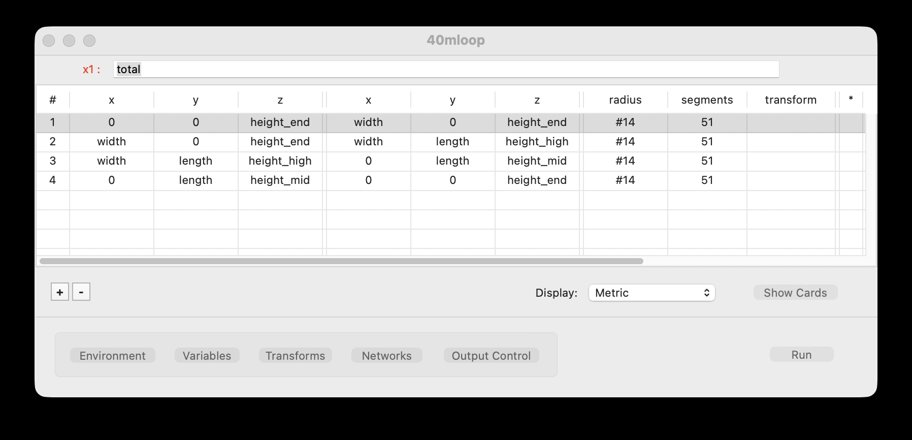
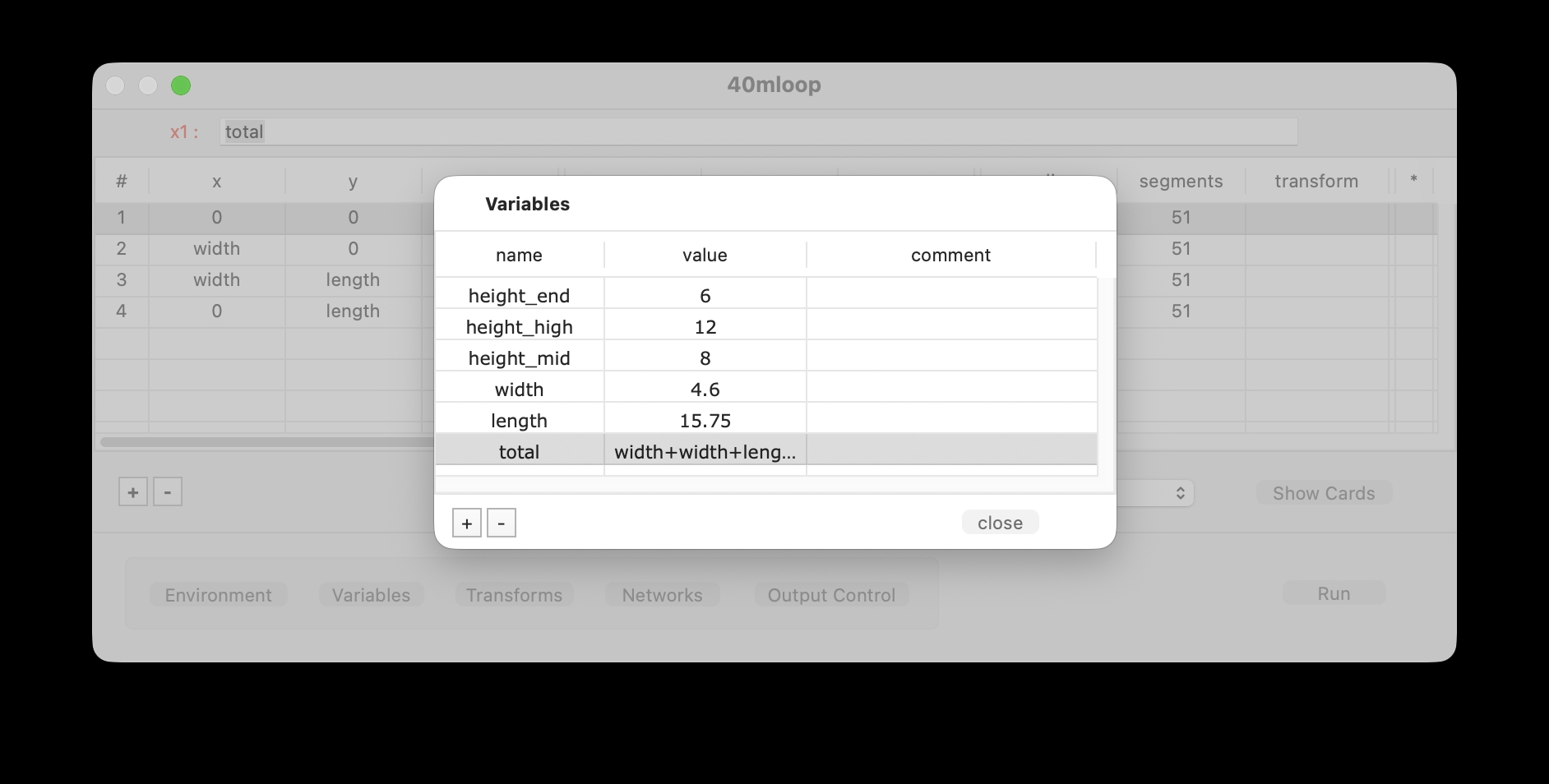
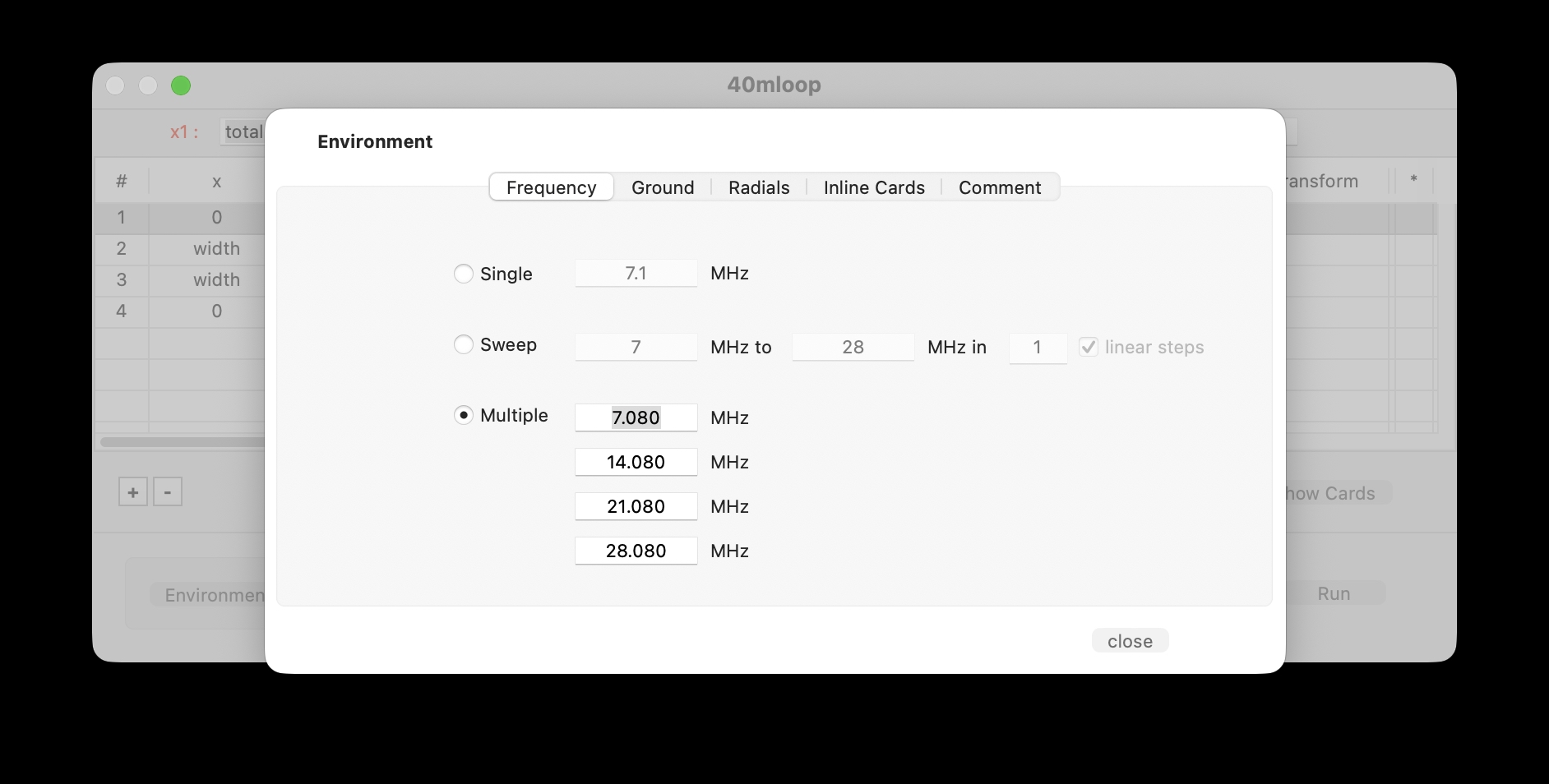
I defined some basic variables I could tweak to optimise the design while simulating it. The environment was set as “Average Ground” with a relative dielectric constant of 13.0 and a conductivity of 0.0050 mho/m. I ran the simulation across several amateur bands to check for any useful performance beyond 40m (7 MHz).
Smith Chart For Several Bands
After some experimenting with the lengths of the sides (within the space the antenna has to fit), I was able to obtain this simulation of the feed-point impedance.
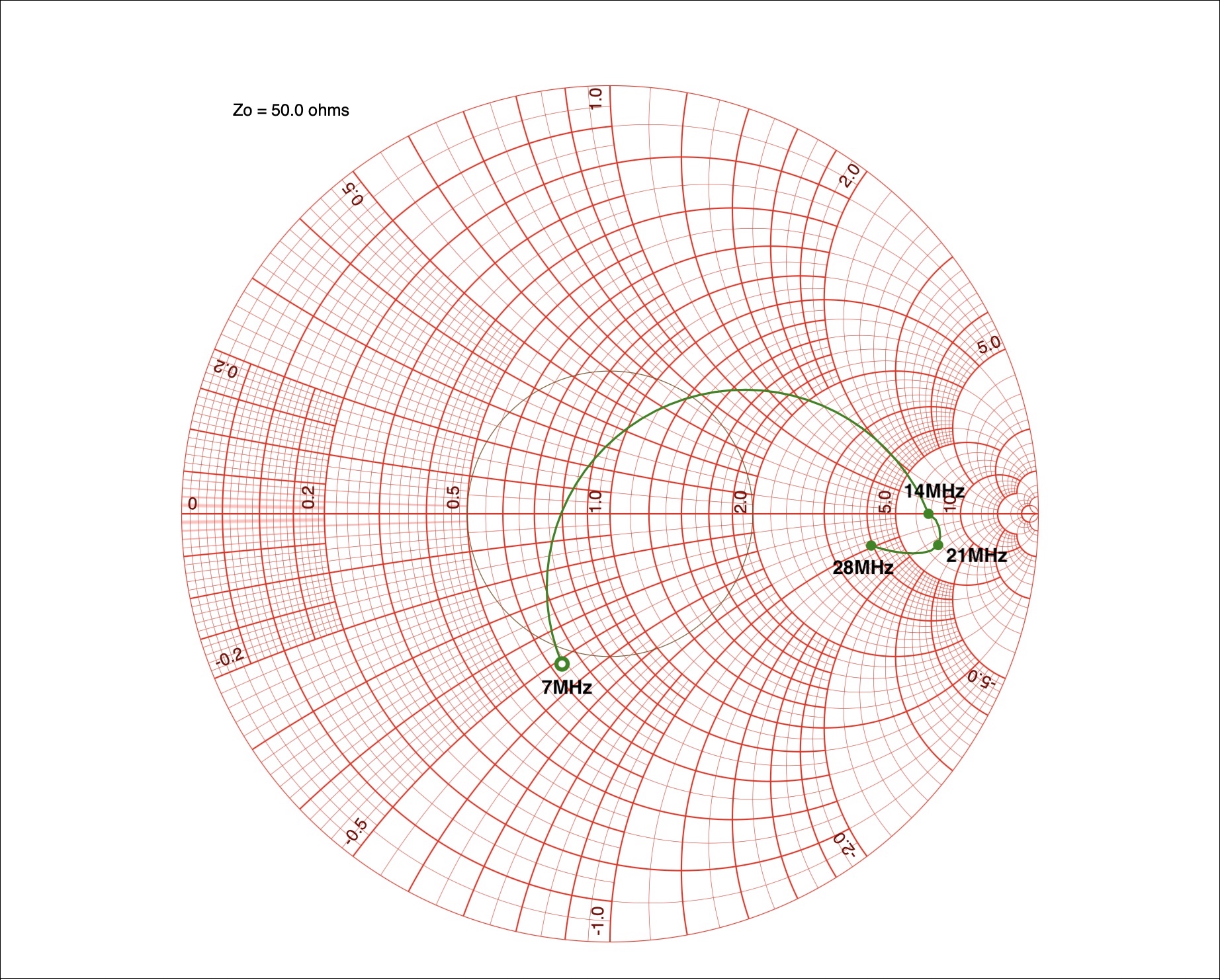
Not a perfect match to 50 ohms by any means, but within the range of a tuner. The impedance at spot frequencies is:
| Frequency | Z | VSWR |
|---|---|---|
| 7.080 MHz | (31.800 - i 25.795) | 2.2:1 |
| 14.080 MHz | (339.830 - i 0.024) | 6.8:1 |
| 21.080 MHz | (339.450 - i 121.570) | 7.7:1 |
| 28.080 MHz | (197.270 - i 46.992) | 4.2:1 |
I plan to measure the antenna with a VNA when it is installed, to see how close my simulation is.
Azimuth and Elevation Plots
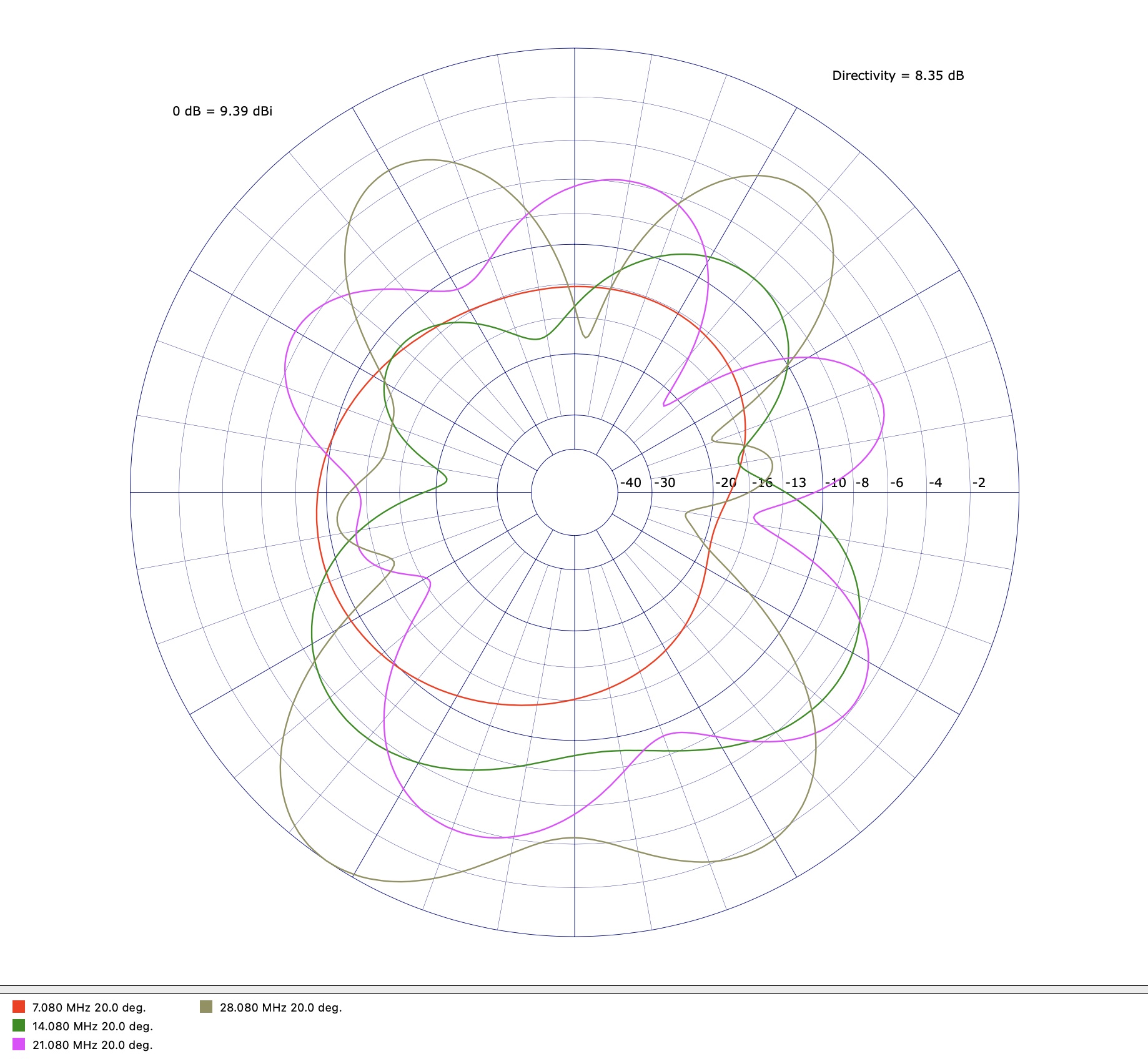
Checking the elevation plot of the antenna, it is clear that most of the signal on 40m is directed upwards - the antenna is a bit of a sky-warmer. The other bands have some directivity at lower angles, making it more useful for distant communications when you want the signal directed to the horizon.
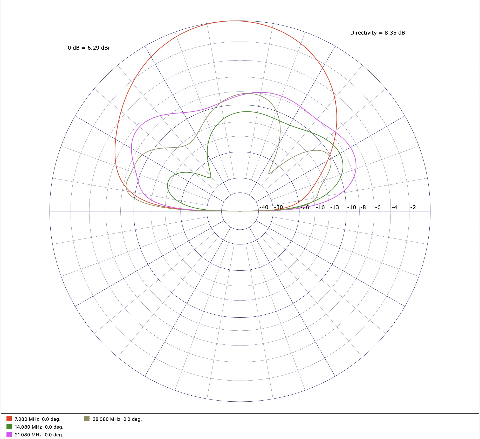
The azimuth plot is a bit of a mess, with no real clear directivity. I had hoped the antenna’s slope might cause some directivity towards the west, but there’s nothing significant.
Conclusion (for now)
I’ve ordered the parts to build the antenna, but a lack of time and serial heatwaves have kept me from doing much in the garden to prepare for antenna construction.
Construction and testing will be in a separate article.