Simple Arduino Temperature and Humidity Logger
I was contacted by a small city archive to provide a temperature and humidity logging system for their store rooms. Heritage items are kept under standardised conditions in storage to prevent (or at least retard) deterioration, pest damage and mould growth; ensuring those conditions are maintained over long periods of time is essential. Commercial data logging systems exist, but are prohibitively expensive for small institutions.
The requirement was for a number of data loggers recording ambient temperature & humidity values every 10 minutes (user configurable). A low-power RF link on 2.4 GHz was investigated for remote reporting sensors, but the RF environment in the archive was inhospitable - thick walls, archive spread over several floors and strong co-channel interference from building WiFi installation. Instead, it was decided to record sensor readings directly on the sensor nodes for periodic collection.
Sensors
I initially planned to use a combination of DS18B20 1-wire temperature sensor and SHT21 humidity sensor on the data logger, both parts I’m very familiar with. I was unable to source sufficient SHT21s, so had to fall back on another humidity sensor - the DHT22. I’d originally considered the DHT22 to be too low specification for this application, until I found an article testing their performance - this, along with some testing of my own convinced me to use them. The DHT22 includes a temperature sensor, removing the need for a DS18B20 and reducing the bill of materials.
Processor Hardware
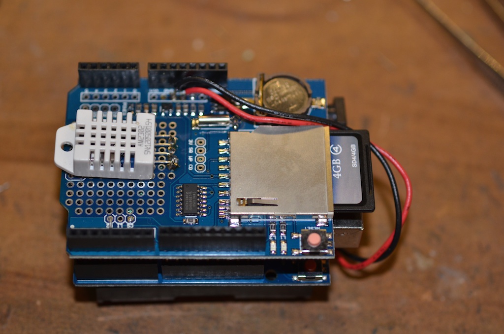
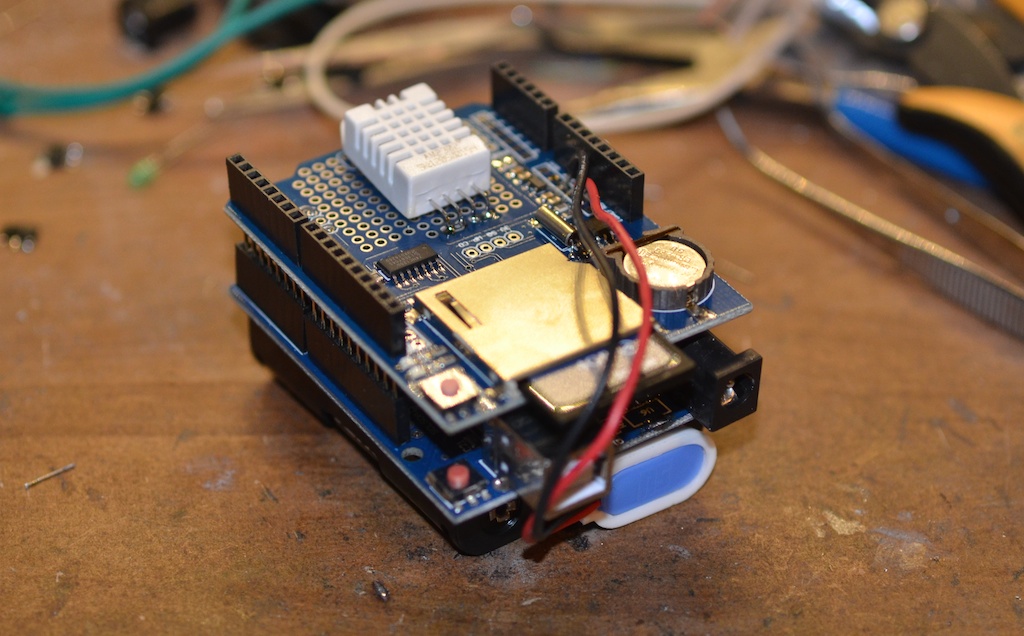
For the sake of rapid prototyping and code-reuse, the Arduino platform was used to interface the sensors with the recording media (an SD card). A PCB was designed and about to be sent for fabrication when I became aware of cheaply available clones of both the Arduino UNO platform and a combined real-time clock & SD card interface shield. These could be purchased for less than the cost of fabricating and stuffing one custom PCB; four were ordered for testing.

Hardware Power Consumption
The clone Arduino UNO and RTC / SD card boards drew ~65 mA at 5V DC when programmed to write incrementing numbers to a file on a 4 gigabyte Kingston class-4 SDHC card. This level of power consumption gave a calculated battery life of ~2 days if powered from three good quality alkaline AA cells - dire. Removing the power LEDs from both boards reduced the current to 20mA, a big improvement but still an order of magnitude higher than I’d like.
As I was injecting power directly into the 5V DC port on the Arduino, I didn’t require the on-board voltage regulator any more, I could remove this and save a few mA of quiescent current - total current draw was down to 16mA. I could probably have saved more current by removing the USB interface circuitry too, but this was still required.
Software Power Consumption
The data loggers will only need to record a few times per hour, the rest of the time they can power down to save the batteries. It was also decided to use the SDFAT library to access the SD card rather than the SD library, because the SD library was reported to leave the SPI bus clock active after finishing accessing the SD card, this leaves the card awake and consuming power.
A sleep routine in the JeeLib library was used to power down the microcontroller, only waking up when prompted by the watchdog timer. This reduced the current consumption to 2 mA with no SD card in the socket, rising to 3.7 mA with the Kingston card.
Software
The main active loop of the software takes around one second to run, during which it reads both the DHT22 sensor and the RTC, activates the SD card and appends the date/time and sensor readings to a file on the SD card. The microcontroller then sleeps for ten minutes, before making the next reading. There is nothing special in the software, it’s really a few lines of code gluing library functions together. The software isn’t available any more, because it’s really not the best way to do this.
Current consumption is 3.7 mA in sleep mode, mostly due to the SD card, DHT22 sensor and USB hardware on the Arduino, rising to ~10 mA during a wake period. This should allow around 50 days operation between battery changes - long enough to evaluate the performance of the sensor system and to design a fully custom low power solution.
Results
Of the four sensor packages installed, three worked almost flawlessly for two months, the other was intermittent from day one. Enough data was collected to evaluate the archive conditions, but ultimately these hacked together prototypes were not suited for long term use.
The project did inspire other research and designing in the field of low power sensors, some of which are documented elsewhere on this website, try the tags on this post or the search function of the website for more information.

