Capri Transistor 7 - Resurrection and Repair
Introduction
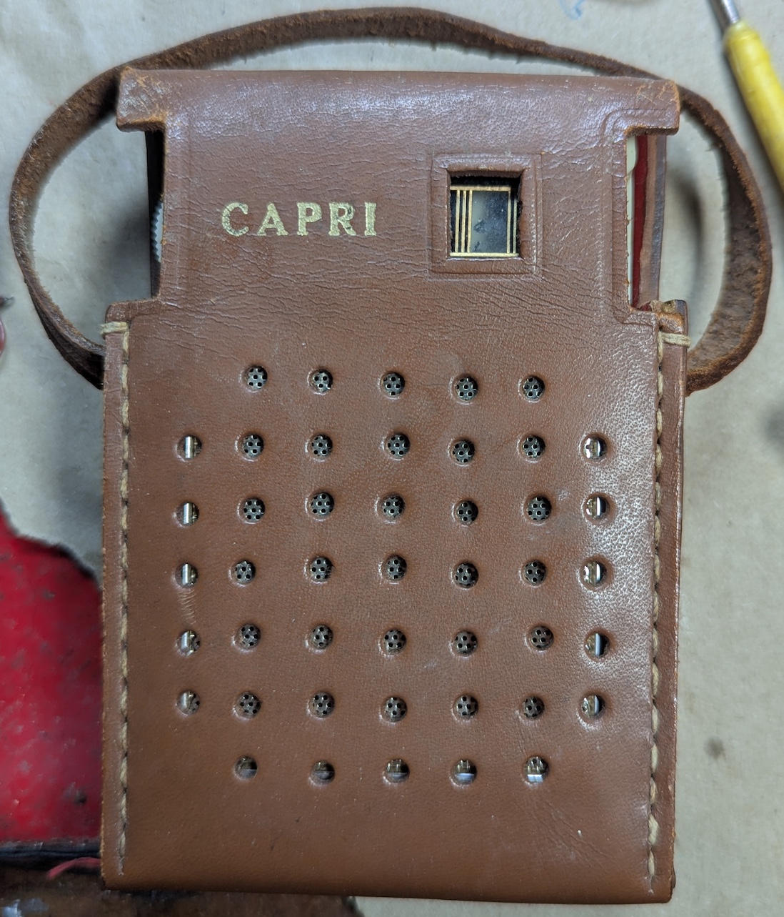
Hunting in the shed for something else, I happened upon a box of old radios from an estate sale. Among the plastic-cased Japanese or Taiwanese AM radios was this leather-cased specimen. A post-it note on the back just said: “NOT WORKING”, so I brought it to the healing bench
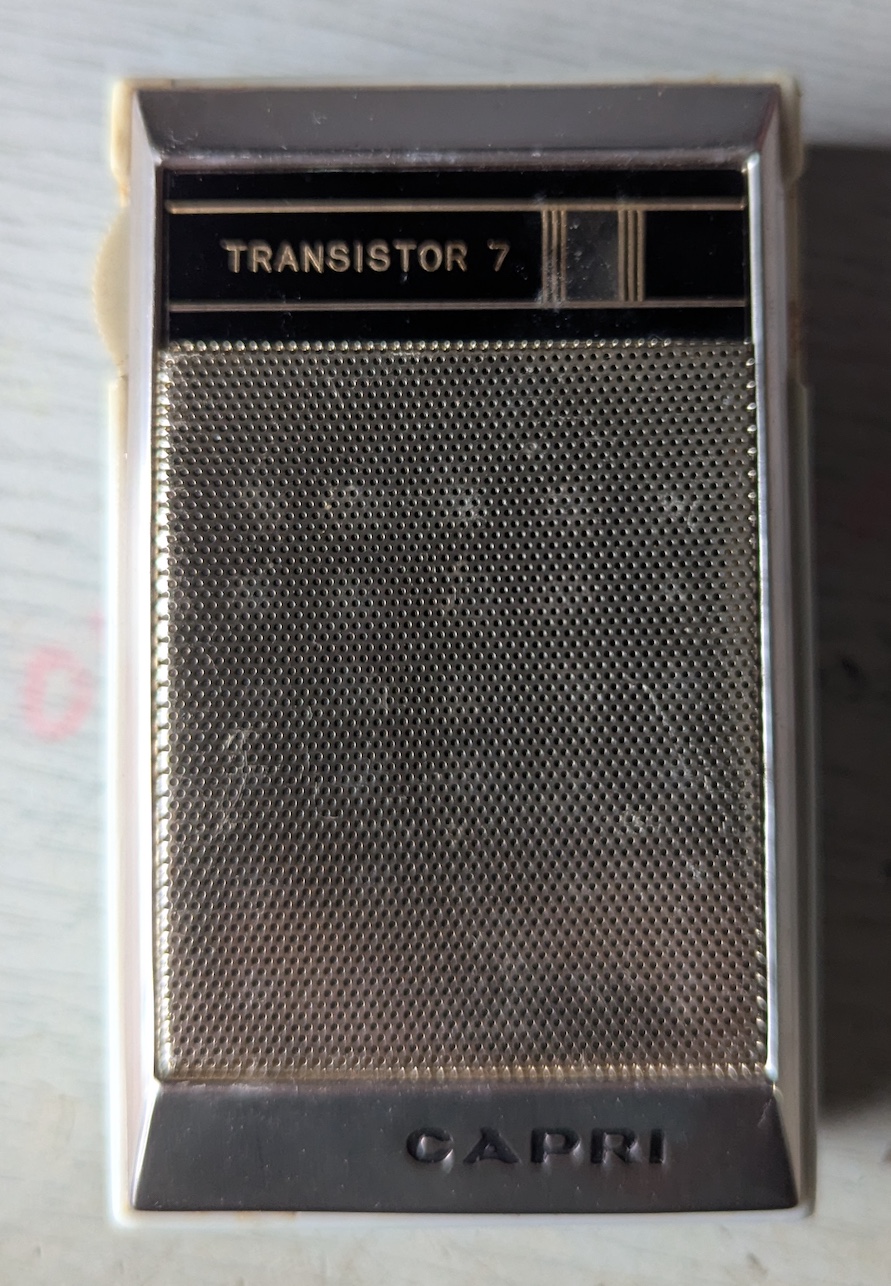
Uncased, it was just a plastic radio with some gold paint.
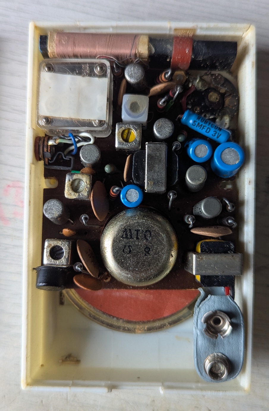
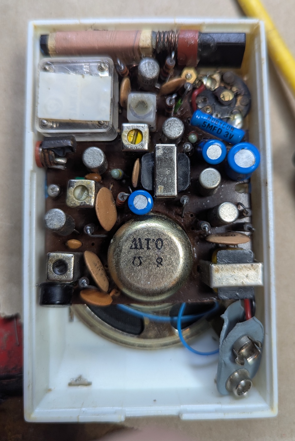
With the back off, it was the usual Medium-Wave only AM radio made with bench-sweeping parts; two IF stages, a transformer-coupled amplifier and a tiny ferrite rod antenna.
Diagnosis
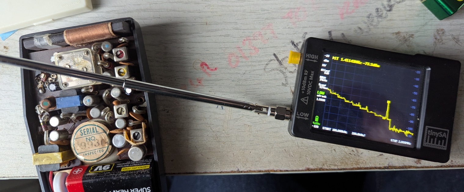
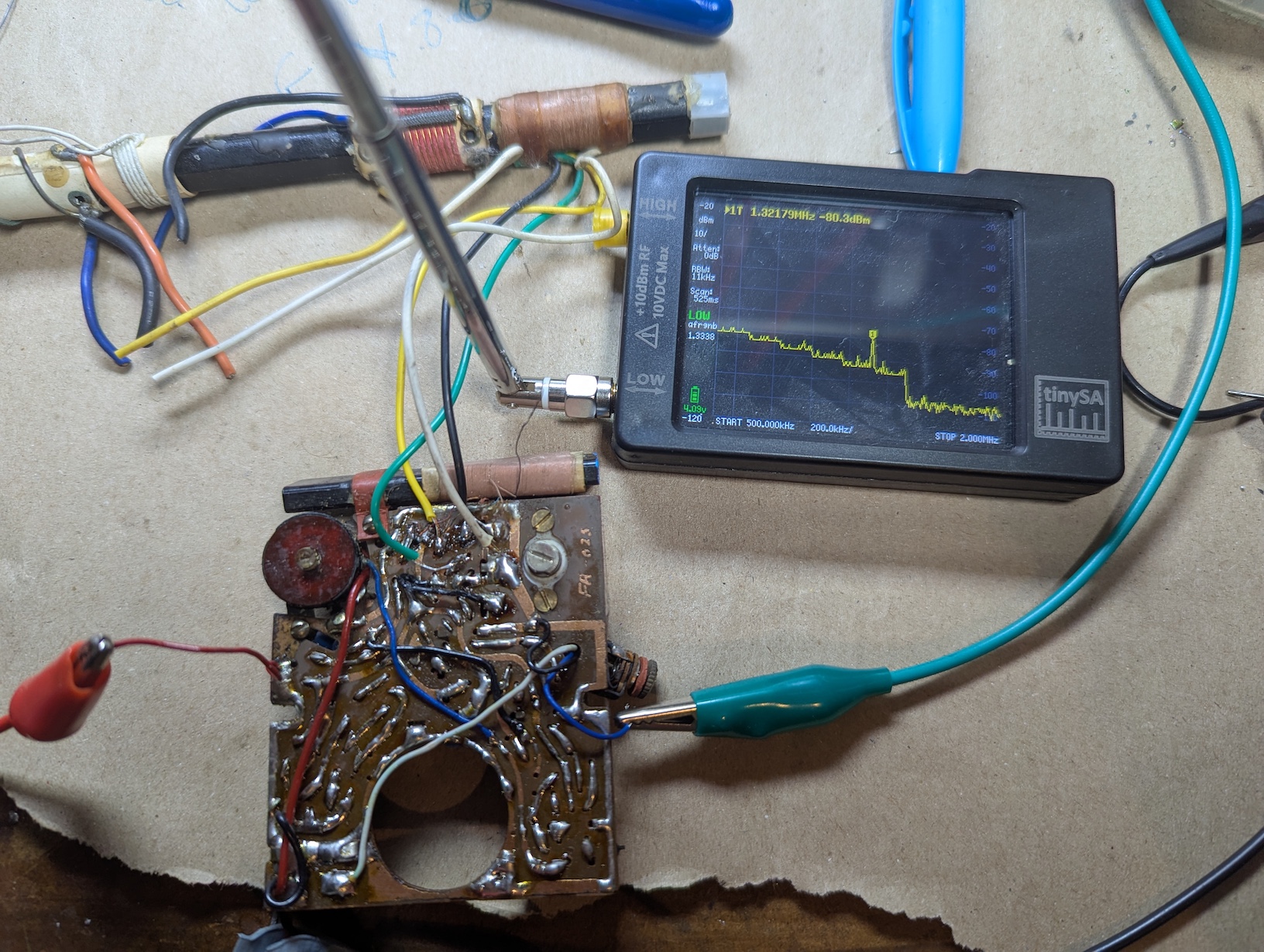
With a fresh 9V battery connected, the radio made a crunching noise from the speaker and a very soft hiss. The volume pot was scratchy, the tuning dial moved, but nothing was received. To check whether the local oscillator (LO) was running, I placed a short whip antenna connected to a TinySA spectrum analyser across the back of the radio and swept from 300kHz to 2 MHz. I should see a peak in the spectrum that shifts as the tuning dial is adjusted.
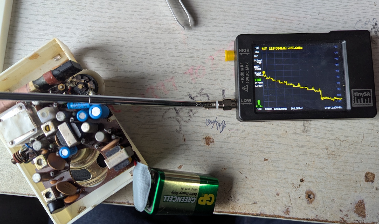
No peak was seen, suggesting that the LO was either very low or not running at all. I checked a known running radio to confirm the diagnosis and saw a clear peak in the spectrum at the LO frequency.
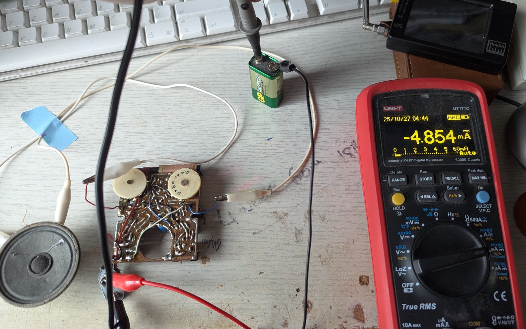
To get the radio PCB out of the case, I removed the headphone jack socket and de-soldered the speaker. I could then wire in an external speaker and check the radio’s current consumption with a multimeter. It showed around 5 mA, which is reasonable given no received signal and low audio.
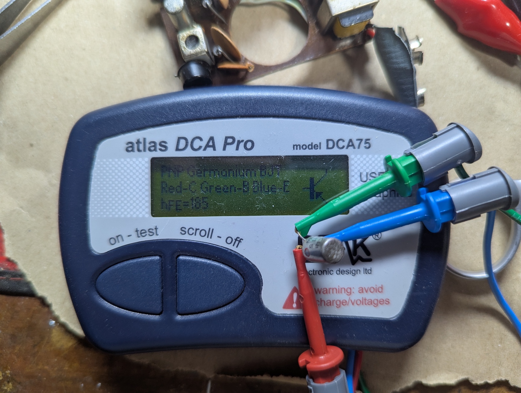
Close inspection of the board didn’t reveal any broken traces or particularly crappy solder joints. Pressing with metal tweezers onto the base pin of the oscillator/mixer (converter) transistor did cause a loud noise and the occasional reception of Radio 5 Live (a very strong signal in my area). This suggested to me that the radio was acting as a TRF set rather than a Super-Het. I suspected the transistor and removed it for testing. It was fine.
Resurrection
With the transistor replaced, I still couldn’t detect the LO. Not having a circuit diagram to hand for this radio, I made an educated guess that the mixer/oscillator transistor would be connected to the ferrite rod antenna. So I started beeping out the connections to the antenna coils. One set of coils came up open-circuit.
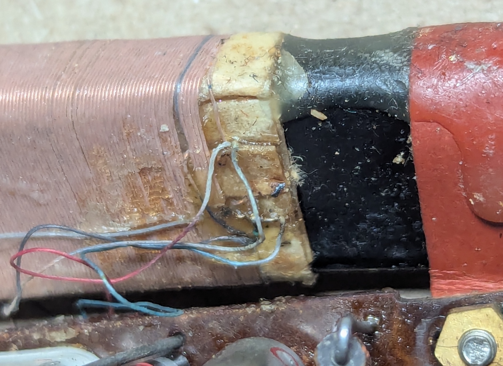
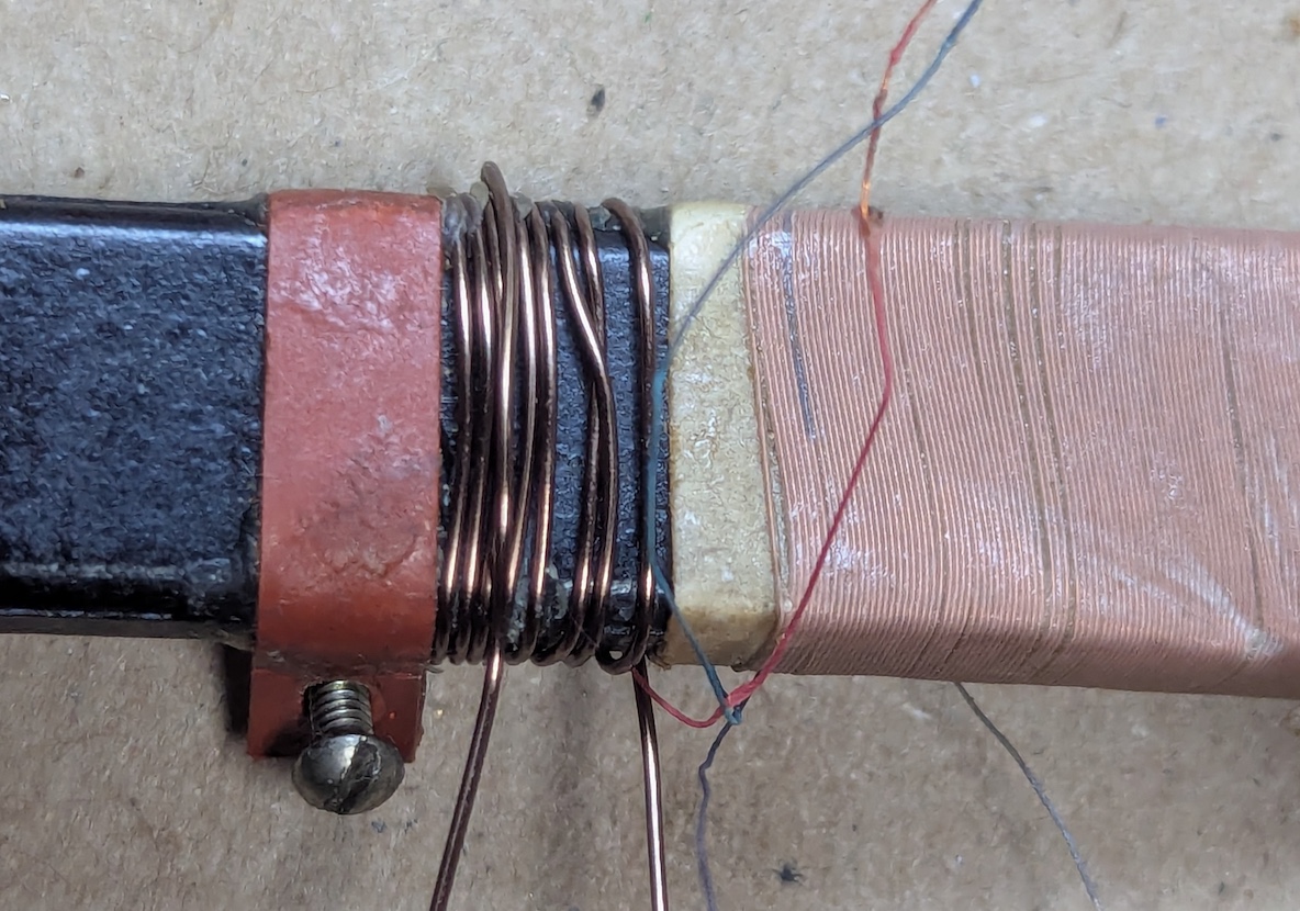
The open winding was just a few turns wrapped alongside the main winding. Probably some coupling arrangement. I made a note of where the various leads from the antenna coils were soldered to the radio PCB, then replaced the whole bar antenna with a much larger one from a scrapped Robert’s Radio.
With the spare antenna connected, I could see a LO signal on the spectrum analyser and hear several stations as I tuned around. I was prepared to leave it there; the larger antenna wouldn’t fit in the radio case and was, anyway, far too good for this cheap radio. I put it aside for the evening, but it nagged at me.
Repair
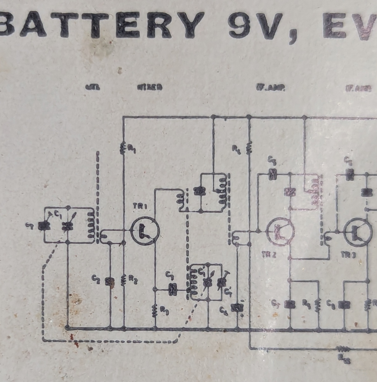
It’s a fact that all these types of radios are just variations on a theme, a fairly standard circuit modified to suit whatever parts were cheap the week of manufacture. A different radio had a pasted-in circuit diagram. Using this as a reference, I measured the inductance of the coupling coil on the Robert’s bar antenna, then worked out how many turns I’d need on the bar in this radio - about 10 turns of wire for the coupling winding. I used too-thick wire, but it was what was on hand, to wind a new coupling coil on the original ferrite rod antenna.
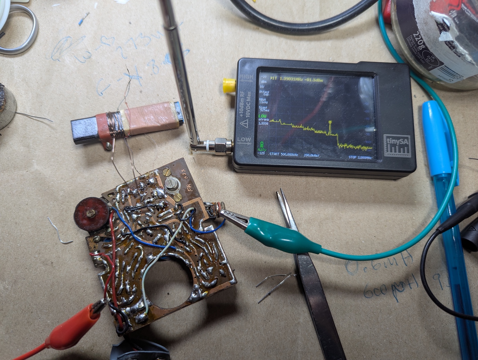
With the new coil connected to the radio, the LO was visible on the spectrum analyser.
Misc Repairs
I doused the volume pot with Dexoit to clean it, and ran some fine-grit paper through the switch contacts to remove oxidation. I replaced the AGC capacitor, too, as the radio had a loud whine when tuned to a station. The original value was 6uF at 18V. I replaced it with a 10uF at 25V. I didn’t replace any other capacitors.
The radio went back into the case easily, although the tuning dial binds up in some positions. I probably need to remove the PCB again and shim it to make the dial fit correctly. If I do pull the PCB again, I’ll probably do a prophylactic replacement of the remaining electrolytic capacitors.
Conclusion
This was a more interesting repair than I expected. Starting off, I fully expected to just need to replace a transistor and re-cap the radio. Instead, I got the chance to dive into the antenna side of things and make some educated guesses and rough calculations to rewind the antenna.
It’s not a fantastic radio by any means; it hears the same stations a similar radio does, and about half as many stations as my DEEPELEC DP-666 or Icom IC7300 can hear at night. I’ll keep it as a nice, cased example of a cheap radio.