Heart Blinkenlights - Charlieplexing LEDs
Introduction
I wanted to make something for my partner for Valentine’s Day 2014. Browsing the local Maplin shop, I came across a Velleman kit in the shape of a heart with approximately thirty 3mm red LEDs. In its standard form, the kit just flashes all the LEDs on and off at a few Hz - it’s just a two transistor astable circuit - nothing too exciting. I bought it and started thinking about how to upgrade it once I had it back in the workshop.
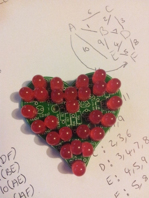
First off, I ditched the supplied LEDs switchig the out for some 5mm ultra high brightness ones, unfortunately I ordered 8mm by mistake so some filing and brute force was needed to get them to fit the PCB.
I’d wanted to try Charlieplexing for some time, so this seemed like a good opportunity. I had some PIC16F883 devices in SMT form in the spares bin, these are small enough to fit on the back of the heart PCB and will run with no extra parts - that made selection of controller easy - use those.
LED Placement

At the time I soldered the LEDs on the PCB I hadn’t though too much about how to address them via charlieplexing, so I just had them in pairs, anti-parallel. I can always fix the addressing in software - however this does make for some odd looking code at times. It would have been much nicer to have been consistent with placing the LEDs such that the topmost of each pair was always at the lowest (or highest) address. The image shows how a few of the LEDs had to have some extreme modification with a file to fit the board.
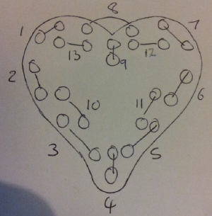
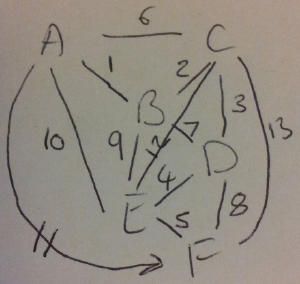
To charliplex 26 LEDs requires 6 wires. Numbering the LED pairs and drawing the connection graph gives the addresses and the data bytes we needs to control which LED is on at any given time.


This gives the following mapping:
| Wire ID | LEDs | Wire Colour |
|---|---|---|
| A | 1,6,10,11 | Blue |
| B | 1,2,7,9 | White |
| C | 2,3,6,12,13 | Orange |
| D | 3,4,7,8 | Yellow |
| E | 4,5,9,10,12 | Brown |
| F | 5,8,11,13 | Red |
Animation
I decided I wanted a chasing light animation around the LEDs, speeding up each pass followed by a left-right wipe and something else (undecided as i fired up the compiler). The initial code I wrote was just to test the LEDS, it cycles though each LED pair address and alternates which of the pair is on - this was to check the wiring was correct and to form a basic program to build upon.
Two have more than one LED appear to be on in a charlieplexing scheme you need to flash the LEDs quickly and reply on persistence of vision to make them seem on fully.
The way I implemented the address and data scheme is far from optimal - given more time I’d have written the code in a more sensible style, however the microcontroller is running at 8 MHz so I have CPU cycles to spare and there is more than enough program space for the code as it stands. If I wanted to implement flashier animations I’d probably have to compress the the address and data tables to fit the PIC’s ROM - or re-wire the LEDs to fit a ’nicer’ addressing scheme.
Code
The PIC code was compiled with CCS C for the PIC16 series devices. It should port to SDCC or similar or to the Arduino with minimal changes - basically the register that sets the tri-state behavouor of the bus and the data registers are the only thing to change. case
byte PORTC = 7
unsigned int a,f;

unsigned char LEDADDR[] = {3,6,12,24,48,05,10,40,18,20,33,24,17,36,18,40};
unsigned char LEFT[] = {3,6,12,24,36,17,18,40};
unsigned char RIGHT[] = {40,18,20,10,5,33,48,24};

unsigned char fcount = 32;
unsigned char FRAMES[] = { 2,1,
                           2,4,
                           8,4,
                           16,0,
                           16,32,
                           4,1,
                           2,8,
                           32,0,
                           2,16,
                           4,16,
                           32,1,
                           8,0,
                           1,16,
                           4,32,
                           16,2,
                           8,0
                           };

unsigned char LEFTFRAME[] = { 2,1,
                              2,4,
                              8,4,
                              16,8,
                              32,4,
                              16,1,
                              16,2,
                              8,0};

unsigned char RIGHTFRAME[] = { 22,0,
                              16,2,
                              16,4,
                              2,8,
                              4,1,
                              1,32,
                              16,32,
                              16,8};


void trace()
{
  int ff = 0,loopcount = 500;
  while (loopcount > 0)
  {
    for (a = 0; a < 16; a++)
    {
       set_tris_c(~LEDADDR[a]);
       for (f = 0; f < 2; f++)
        {
          if (FRAMES[ff] != 0)
            {
              PORTC = FRAMES[ff]
              delay_ms(loopcount);
             }
          ff++;
         }

        if (ff == fcount) ff = 0;

      }
    loopcount -= 100;
  }

}

void allon(int count)
{
//all on
int ff=0;
while (count > 0)
  {
for (a=0; a < 16; a++)
  {
      set_tris_c(~LEDADDR[a]);

    for (f = 0;f < 2; f++)
    {
      if (FRAMES[ff] != 0)
      {
        PORTC = FRAMES[ff];
          delay_us(50);        // pauses for 50 microseconds
       }
      ff++;
     }
  if (ff == fcount) ff=0;

  }
  count--;
  }
}

void left(int count)
{

int ff=0;
while (count > 0)
  {
  for (a = 0; a < 8; a++)
    {
      set_tris_c(~LEFT[a]);

      for (f = 0;f < 2; f++)
      {
        if (LEFTFRAME[ff] != 0)
          {
          PORTC = LEFTFRAME[ff];
            delay_us(50);        // pauses for 50 microseconds
           }
        ff++;
       }

  if (ff == 16) ff = 0;
  }
  count--;
  }
}

void right(int count)
{
int ff = 0;
while (count > 0)
  {
  for (a = 0; a < 8; a++)
    {
     set_tris_c(~RIGHT[a]);

      for (f = 0;f < 2; f++)
      {
        if (RIGHTFRAME[ff] != 0)
          {
          PORTC = RIGHTFRAME[ff];
           delay_us(50);        // pauses for 50 microseconds
           }
        ff++;
       }

  if (ff == 16) ff=0;
  }
  count--;
  }
}

void alloff(int count)
{
  PORTC=0;
  delay_ms(count);
}

void dash()
{
  allon(1000);
  alloff(300);
}

void dot()
{
  allon(333);
  alloff(300);
}
void space()
{
  alloff(700);
}


void morse()
{
 // send some morse here if wanted.


 // demo
dash();
dot();
dot();
space();
dot();
}

void main()
{

   setup_adc_ports(NO_ANALOGS|VSS_VDD);
   setup_adc(ADC_OFF);
   setup_spi(SPI_SS_DISABLED);
   setup_timer_0(RTCC_INTERNAL|RTCC_DIV_1);
   setup_timer_1(T1_DISABLED);
   setup_timer_2(T2_DISABLED,0,1);
   setup_comparator(NC_NC_NC_NC);
   setup_oscillator(OSC_8MHZ);

while (1)
{
  trace();
  allon(1000);
  left(1000);
  right(1000);
  left(500);
  right(500);
  left(250);
  right(250);
  allon(500);
  PORTC=0;
  morse();
  delay_ms(1000);}

}
Once again - this is very rushed code - there are multiple ways to improve this, I just didn’t have time.
Result
The video shows one run through of the code - I may make some edits if I get any more time to play with the project before I had it over.
